This research developed theory and software for commercial optical lens manufacturing and aircraft canopy restoration, drawing upon intellectual disciplines including mathematical modelling, numerical analysis, and research software engineering. Today, this research would naturally categorize into the new and rapidly developing field of computational science and engineering.
This research experience built upon the Porsching and Hall mathematical model for abrasive material removal [PHBE1993].
The publication [PHBE1993] focuses on the mathematical model of material removal with application to CNC finishing in two-dimensions, the topic of my undergraduate thesis which was directed by Porsching and Hall [E1992, link]. I developed software implementing the Porsching and Hall mathematical model of material removal with application to CNC finishing.
The operator controlled finishing research experience required me to develop a mathematical model for the kinematics of the Draper type polishing machine, a major contribution to this research experience. I mathematically modeled the commercially used draper machine and developed software an optics manufacturer would use. These results are reported in the thesis [B1999].
The reader is invited to review the publication on operator controlled abrasive finishing of aspherical optical surfaces [PH1996]. The general results in Section 2 of that publication immediately apply to the Draper type polishing machine and there should be no need to report these details here. We focus on developing the kinematics for the Draper type polishing machine which is the input to the theory in [PH1996].
The image for this webpage under the heading [Operator Controlled Finishing Aspherical Optical Surfaces] is permitted to be taken from the web articles [USAFImage] and [USAF].
OUR RESEARCH GROUP
Our research group included principal investigators Thomas A. Porsching and Charles A. Hall as well as graduate student researchers Therese L. Bennett and John M. Ernsthausen.
As a first year graduate student in applied mathematics at the University of Pittsburgh, I am honoured to be a graduate student researcher for Thomas A. Porsching and Charles A. Hall. The mathematics department usually funds first year graduate students as teaching assistants.
The Erdös Number Project [Erdös] studies research collaboration among mathematicians. Authors are ranked by collaborations with authors who have published with Erdös and his coauthors. My publication [PHBE1993] with Charles Hall makes my Erdös number 3:
Paul Erdös → John Kennedy → Charles Hall → John Ernsthausen.
THE PROJECT
Contraves Inc. our industrial partner needed mathematical guidance to efficiently fabricate the world's largest single-piece optical element, an 8.3-meter telescope primary mirror. Contraves undertook a contract for grinding and polishing the 8.3-meter telescope primary mirror from a mirror blank fabricated by Corning Inc. (NYSE: GLW) which measured over 27 feet in diameter and is about nine inches thick. The following press release provides context and perspective on the optical fabrication process [Press].
This component now serves as the principal optical component for the Subaru Telescope, sponsored by the National Astronomical Observatory of Japan [NAOJ]. View polishing and transportation photos at this link, especially the image the primary mirror being transported on the highway which depicts the transportation of the huge mirror blank on Interstate I-79 near the Wampum Industrial Facility.
The massive rock surroundings at the Wampum facility made this site an ideal location for optical fabrication because the temperature remains extremely stable (about 55 degrees F), humidity is reduced (about 50%), and the environment is basically vibration free.
OPERATOR CONTROLLED FINISHING
Operator controlled (OC) abrasive finishing of aspherical optical surfaces applies a general mathematical theory of abrasive material removal developed by Porsching and Hall in [PHBE1993] to determine non-negative dwell times for polishing machine settings [PH1996, PHB1998, B1999]. The polishing machine settings in OC finishing do not vary continuously. The operator must choose a setting. The OC algorithm then determines an optimal dwell time for that machine setting.
The optic is ground from a mass of material called the workpiece. An optician chooses a polishing machine setting to rub away a profile of material desired to be removed called an error profile.
The kinematics of the polishing machine define the instantaneous amount of material removed from the workpiece per unit of time, the instantaneous material removal rate. Provided certain assumptions hold, one can justify averaging the instantaneous material removal rate to obtain the (average) material removal rate which expresses the average amount of material removed from the workpiece through abrasion in increments of average time. OC polishing computes the (average) material removal rate associated with a polishing machine setting.
The ideal Draper polishing tool is freely pinned. The freely pinned situation occurs when there is negligible friction on the pin connecting the polishing pad with the polishing tool. Here we consider only freely pinned polishing machines and assume that the polishing machine setting leads to an angular independent material removal rate.
A material removal profile globally accumulates the amount of material removed by each rub, a polishing machine setting at its dwell time. Sufficient density in the coverage of the tool center path as well as (quasi) periodicity are expected to lead to angular independent material removal profiles.
OPERATOR CONTROLLED MATERIAL REMOVAL STRATEGY
The goal in operator controlled (OC) finishing is to identify ahead of time a non-negative dwell time for a specified polishing machine setting such that the material to be removed optimally matches a given profile of material desired to be removed, the error profile. An OC material removal strategy determines the best non-negative dwell time. Here best depends on the norm used [PHB1998, B1999].
The optimization process just described would be acceptable if the material removal strategy mathematically reproduced the error profile. In other words, we seek a material removal strategy such that the mathematical difference of the material removal profile with the error profile is the zero profile. For optical surfaces, the shape of the final optical surface is sought without regard to the absolute datum of that shape in the workpiece. A best minimax optimization problem is formulated in quotient spaces [PHB1998, B1999].
In the design of an optimal material removal strategy, an operator chooses Draper machine settings. The optimization problem identifies an optimal non-negative dwell time for each setting. The finite linear combination of material removal rates with the optimal dwell times is a best operator controlled match possible to the error profile using the chosen polishing machine settings.
The operator is responsible for the material removal strategy and experience guided by software is welcomed. An effective strategy will reduce the error profile to within a prescribed tolerance.
THE DRAPER MACHINE MATERIAL REMOVAL RATE
The author along with T. Porsching, C. Hall, and T. Bennett visited the Wampum facility roughly a year prior to the delivery of the blank for the 8.3-meter telescope primary mirror. Opticians demonstrated to us the Draper polishing machine. The polishing machine has a simple design, yet it exhibits a variety of material removal rates. This Draper type polishing machine intends to imitate the polishing stroke a human might make.

Schematic for a Draper type polishing machine.
The workpiece is mounted on a circular bed that rotates counterclockwise with constant velocity about its center . A circular abrasive pad surface of radius is freely pinned at to a beam . The surface is assumed to maintain constant pressure and shape with the workpiece. The beam is free to slide in a collar at and is driven by a crank arm that rotates clockwise with constant angular velocity .

Draper schematic.
The parameters, their values, and their descriptions for the Draper type polishing machine we consider are as follows:
Crank radius NP:
NP has value [8 inches]
Horizontal distance from O to collar Q:
A has value [36 inches]
Horizontal distance from O to center of the crank N:
B has value [36 inches]
Elevation of collar from horizontal through O:
H will be studied at values [-15, -7.5, 7.5, 15 inches]
Distance from crank pin P to pad center C:
S has value [36 inches]
Elevation of crank center from horizontal through O:
h has value [6 inches]
Radius of circular, time independent, homogeneous pad lamina G:
d has value [2 inches]
Radial spacings:
IM has value [101]
Polar grid angular spacing:
JM has value [365]
Angular velocity of workpiece:
has value [1.05]
Angular velocity of crank:
has value [2.81]
Averaging time:
T has value [300 seconds]
Preston's constant:
K has value [1 units]
Pressure:
p has value [1 PSI]
We develop a mathematical model for the kinematics of this Draper type polishing machine depicted to trace the centroid of the tool pad indicated in image Draper schematic by the point in a coordinate system whose origin is fixed at the workpiece center . Let the crank point have coordinates in this coordinate system. Then by basic geometry and dropping the dependence on , find
\[X = A + B + a \cos \omega t\] \[Y = h - H + a \sin \omega t\]Denote by the time dependent angle that the beam makes with the horizontal. Then
\[\cos \gamma = \frac{X}{\sqrt{X^2 + Y^2}}\] \[\sin \gamma = \frac{Y}{\sqrt{X^2 + Y^2}}\]Given these quantities we can compute the centroid of the tool pad at
\[x_c = B + a \cos \omega t - S \cos \gamma\] \[y_c = h + a \sin \omega t - S \sin \gamma.\]One needs the derivative to obtain the average material removal rate
\[\frac{d}{dt} \gamma = \frac{X \frac{d}{dt} Y - Y \frac{d}{dt} X}{X^2 + Y^2}.\]Consider points on the workpiece expressed in a polar coordinate system. Each point on the workpiece is expressed as a radius and an angle. We seek polishing tool settings that result in average removal rates which have the same radial profile independent of angle. In short, we seek angular independent material removal rates.
The tool center path has a complicated dependence on the polishing tool settings. We observe that the practicing optician will choose polishing machine settings that (at least) have certain mathematical properties. (1) The polishing tool setting results in a (quasi) periodic tool center path. (2) The workpiece has angularly independent coverage. We choose the quasi-periodic average time to be the value for the parameter .
Polishing tool settings that exhibit these properties were found for the Draper type polishing tool. We plot the tool center path for values .
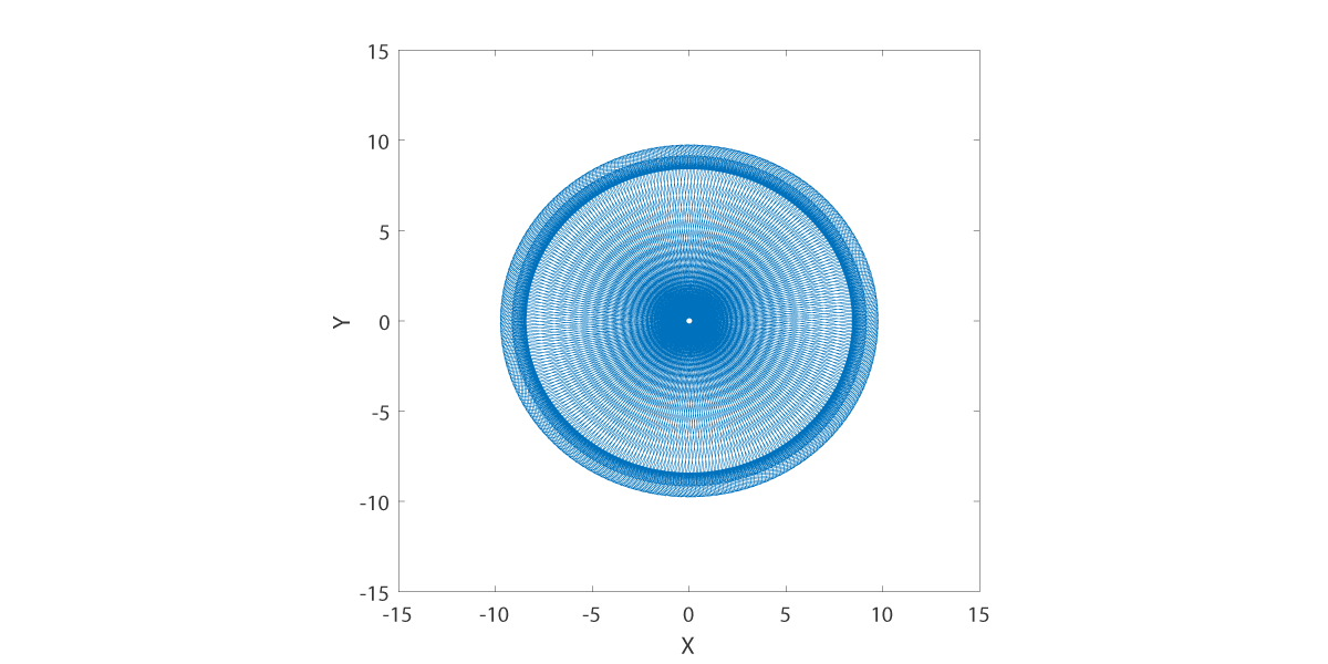
Tool center path at H is -15.0.
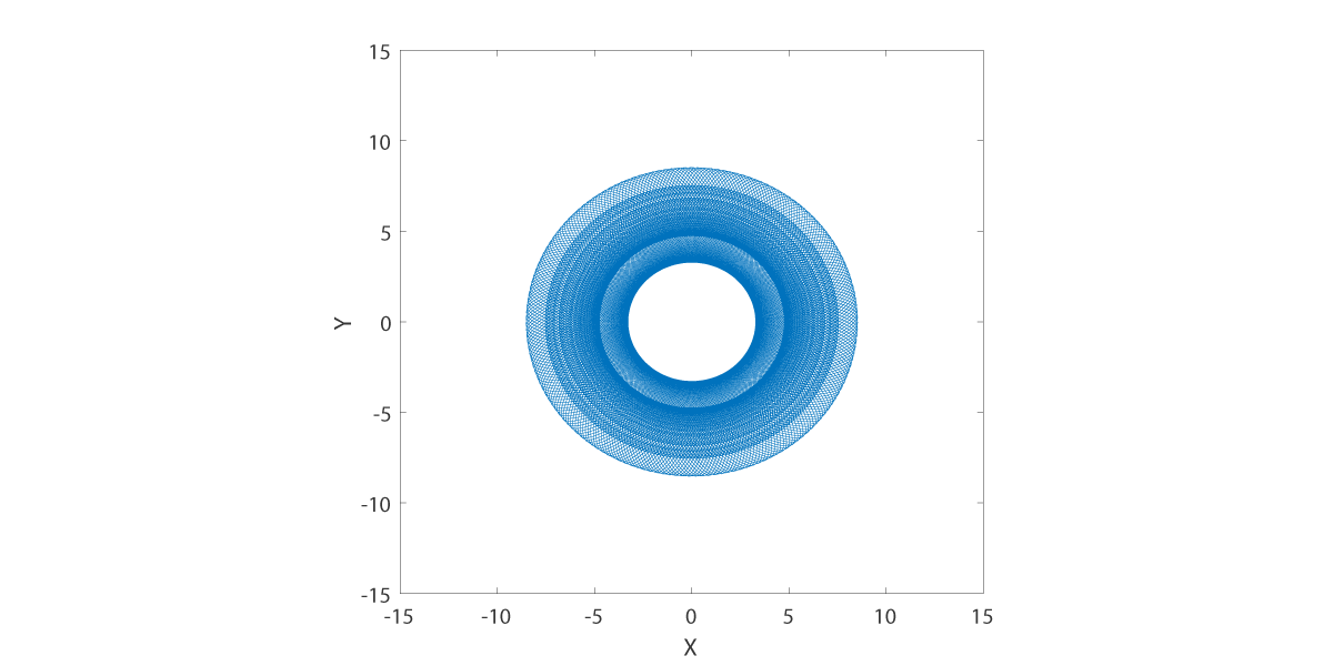
Tool center path at H is -7.5.
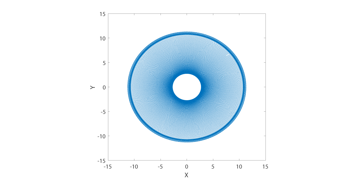
Tool center path at H is 7.5.
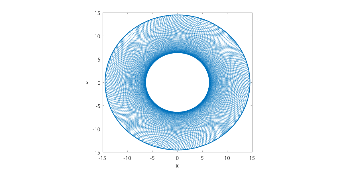
Tool center path at H is 15.0.
We compute the material removal rates following Section 3 of [PH1996] and graph the result.
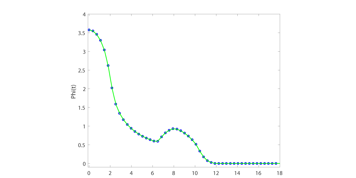
Removal rate at H is -15.0.
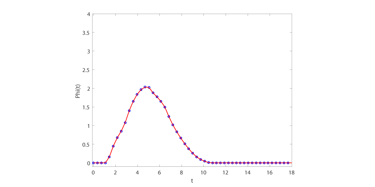
Removal rate at H is -7.5.
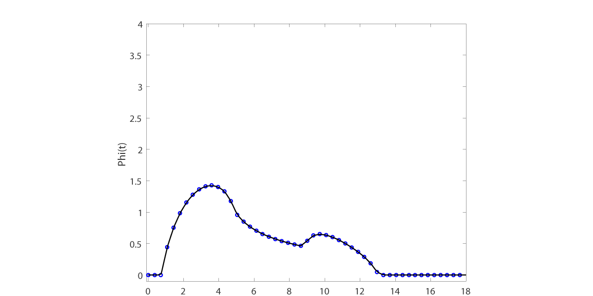
Removal rate at H is 7.5.
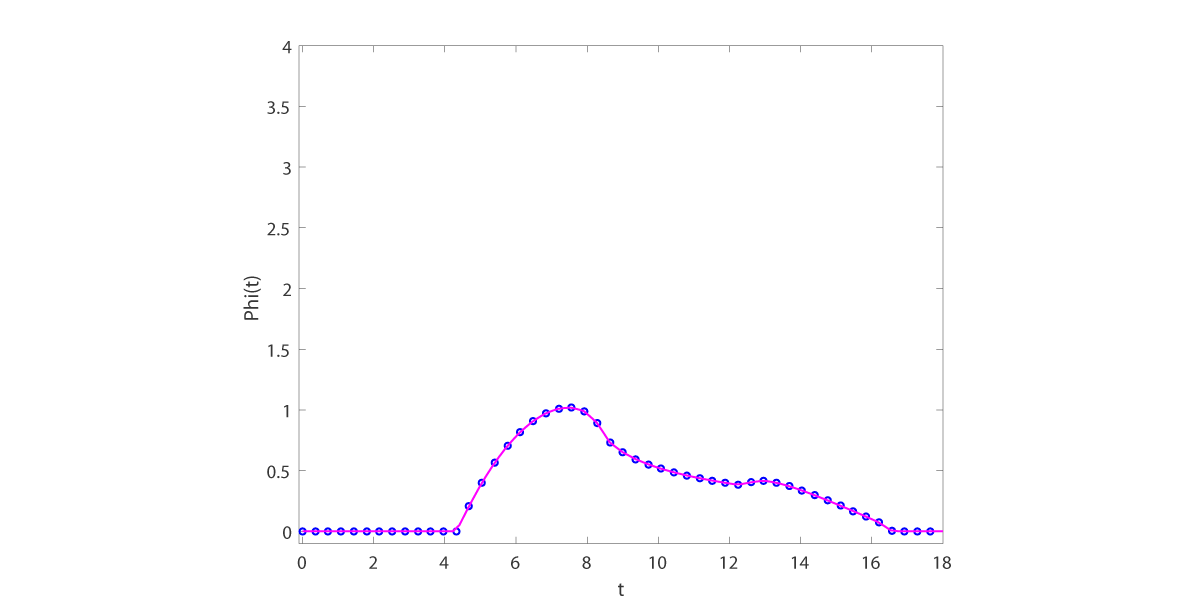
Removal rate at H is 15.0.
LITERATURE
- B1999
- Bennett, T.L.: Best approximation in quotient spaces with application to the finishing of optical surfaces. PhD, University of Pittsburgh, Pittsburgh, PA (1999). [link].
- Erdös
- The Erdös Number Project. [link].
- E1992
- Ernsthausen J.M.: The computer numerical controlled fabrication of optical surfaces.
BPhil, University of Pittsburgh, Pittsburgh, PA (1992).
THESIS COMMITTEE: Prof Charles Hall, Prof Gilbert Strang, Prof Michael Golde, and Prof Kenneth Jordan.
- NAOJ
- Photos of Construction Work of Subaru Telescope. National Astronomical Observatory of Japan. (1999). Accessed: 2016-08-16. [link].
- Press
- Contraves preparing to receive world's largest single-piece telescope mirror. (2009). Accessed: 2015-10-19. [link].
- PH1996
- Porsching T.A. and Hall C.A.: Computationally directed axisymmetric aspheric figuring (after N. J. Brown). Appl. Optics, 35(22), 4463-4470 (1996). [link].
- PHB1998
- Porsching T.A., Hall C.A., and Bennett T.L.: Minimax Approximation of Optical Profiles. SIAM J. Appl. Math., 58(6), 1951-1968 (1998). [link].
- PHBE1993
- Porsching T.A., Hall C.A., Bennett T.L., and Ernsthausen J.M.: A mathematical model of material removal with application to CNC finishing. Mathl. Comput. Modeling, 18(7), 25-40 (1993). [link].
- USAF
- Wayne C.: Shop ensures F-15 pilots can fly with unobstructed vision. 78th Air Base Wing Public Affairs (2009). [link].
- USAFImage
- Sapp S.: Robins maintainers give pilots unobstructed vision. U.S. Air Force photo. [link].